4+ induction type wattmeter diagram
This type of meter is referred to as an electrodynamometer movement. It consists the following parts aDriving system.

Power Measurement
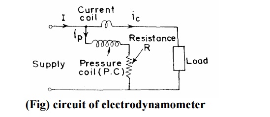
A low range wattmeter is connected to CT and PT as shown in Fig.
. In electrodynamometer type wattmeter moving coil works as pressure coil. One of them is excited by the load current of the main circuit series or current magnets and its exciting coil current. The induction type wattmeter can be used to measure AC power only.
Dynamometer type instrument Ammeter and Voltmeter. Hence moving coil is connected across the voltage and thus the current flowing through this coil is. The induction type wattmeter can be used to measure AC power only.
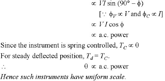
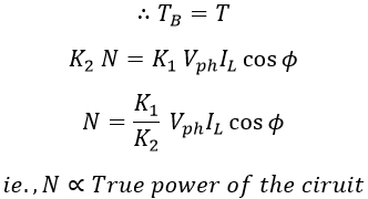
The working of induction type wattmeter is based on the principle of electromagnetic induction. Range extension of wattmeter by CT and PT. We all know Power VI Cos Theta where.
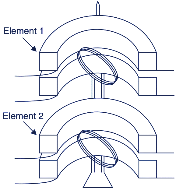
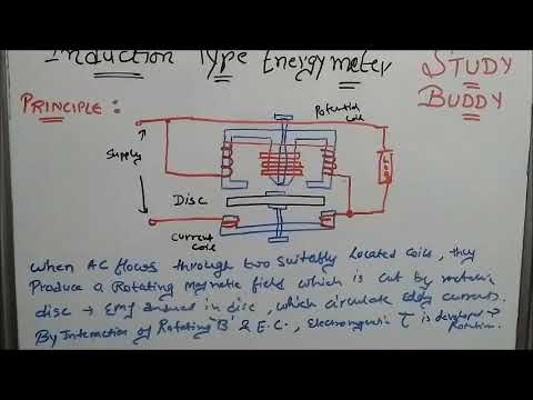
This arrangement creates a. Single-phase induction kilowatt hour meter - Construction. A circuit diagram of a simple electrodynamometer movement is shown in Figure 1.
It consists of two electromagnets called shunt magnet and series. The torque of the instrument is. Actual power Wattmeter reading.
The induction type wattmeter consists of two electromagnets that are placed opposite to each other. 3 a shows the connections of a dynamometer ammeter and Fig. The working of induction type wattmeter is based on the principle of electromagnetic induction.
The induction wattmeter consists of two laminated electromagnets viz. A low range wattmeter is connected to CT and PT as shown in Fig. The CT and PT ratio is known.
3 b that of a voltmeter. The induction-type wattmeter consists of two laminated electromagnets. A thin lightweight disc made up of copper or aluminum is pivoted at the center in the airgap present in between.
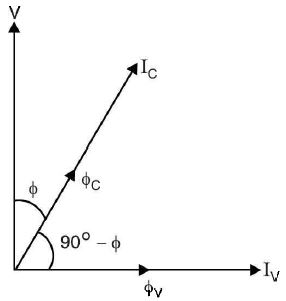
The below shows the construction of an induction-type wattmeter. The phasor diagram of Induction type wattmeter. The working of induction type wattmeter is based on the principle of electromagnetic induction.
Electrical Measurement and Instrumentation. An adjustable copper shading rings are provided on the central limb of the shunt magnet to make the phase angle. Induction Wattmeter is used to measure power in AC Circuits.
Three Phase Wattmeter Working Construction Diagram Electricalworkbook

Solid Oxide Fuel Cell Systems Fault Diagnosis Critical Summarization Classification And Perspectives Sciencedirect

De 13 Lesson 11 Principle Of Induction Type Instruments

Induction Type Energy Meter Ii Electrical Technology Ii Unit 3 Youtube

Pdf Basic Electrical Engineering Shanti Darekar Academia Edu

Induction Type Wattmeter Watt Hour Meter And Dynamometer Type Power Factor Meter
Single And Three Phase Wattmeters And Energy Meters Construction And Principle Of Operation
Electrical Engineering What Is Induction Wattmeters Construction And Its Working

Principles Of Power Systems V K Mehta Complete Book Chapter 6
Induction Type Energy Meter Construction Working Torque Equation
Induction Type Energy Meter Ii Electrical Technology Ii Unit 3 Youtube

Induction Type Meters Electrical4u

Electrodynamometer Type Wattmeter Electrical4u

Induction Type Energy Meter Explained With Clear Diagrams

Wattmeter Types Of Wattmeter Dynamometer Type Wattmeter Induction Wattmeter W Electricity Experiments Electrical Engineering Projects Engineering Quotes
What Will Happen If We Interchange Potential Coil And Current Coil In A Wattmeter Quora

Short Circuit Test Wikiwand